If you’ve ever worked with high-power rotating equipment—think gas turbines, steam turbines, or even large compressors used in power plants or industrial manufacturing—you know how critical even tiny parts are to keeping things running efficiently. Last month, I got a call from a power plant engineer who was pulling their hair out because their labyrinth seals kept failing faster than they should, and they were losing 2% of their turbine’s output to leakage. Turns out, they’d just grabbed a standard off-the-shelf seal without thinking through the unique stuff their high-power application demanded. That call is why I’m writing this today—if you’re in the market for labyrinth seals for high-power gear, there’s way more to it than just picking a part that fits. Labyrinth Seals
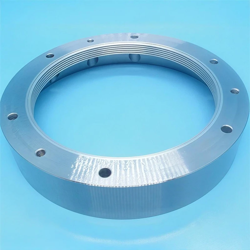
First off, let’s keep it real: high-power applications aren’t like the small HVAC compressors or kitchen appliances you might see seals in. We’re talking about parts that spin thousands of RPM, handle temperatures hot enough to melt aluminum, and have pressure differences so high that even a hairline gap leak can add up to massive energy waste. That’s why the “one-size-fits-all” seals never work here. Let’s break down the key design stuff we (as a labyrinth seal supplier) walk through with every high-power client, because skipping any of these will cost you.
Let’s start with operational temperature and thermal growth—this is non-negotiable for high-power. When a turbine’s cranking at full load, the metal parts aren’t just sitting there nice and cool—they expand, and I mean a lot. I had a client a few years back who specified a seal made of standard carbon steel, thinking it was tough enough. But their turbine’s casing expanded 0.8mm at full temp, while the rotor shaft expanded 1.2mm. The end result? The seal teeth were grinding against the shaft, wearing down fast, and the seal gap got way smaller than it should have been. That led to friction, overheating, and a shaft misalignment—total shutdown time of 3 days, which cost them over $120k in lost production. So for high-power, we can’t just use regular steel. We use alloyed steels, nickel-based superalloys like Inconel, or even stainless steel variants that have matched thermal expansion coefficients with the shaft and casing. It sounds boring, but it works. We also calculate the thermal growth ahead of time, not after the fact, so the initial gap between the seal teeth and the rotor isn’t too tight when things heat up. Another thing here is thermal cycling—if your equipment starts and stops a lot (like peaker power plants that fire up during high demand), the seal has to handle repeated heating and cooling. Regular seals crack after a few hundred cycles, but our high-power ones are engineered with fatigue-resistant materials that can handle thousands of cycles without breaking.
Next up is pressure differential and leakage control, which is the whole point of a labyrinth seal, right? These seals work by creating a tortuous path for fluid (gas or steam) to leak through—each tooth creates a pressure drop, so by the time the fluid gets past all the teeth, there’s almost no pressure left. But in high-power applications, the pressure differences are crazy high—like 100 bar or more in some gas turbines. If the seal isn’t designed for that pressure, you get way more leakage than you should. I’ve seen clients use a 2-tooth seal for a high-pressure compressor, and they were losing 5% of their compressed air to leakage. We switched them to a 4-tooth straight-through seal with stepped teeth, and that dropped leakage to less than 0.5%—game changer. But wait, it’s not just the number of teeth. The tooth profile matters too. For high-pressure, we use knife-edged teeth (thin, sharp) instead of rounded ones because they disrupt the fluid flow more, creating smaller vortices that help bleed off pressure. There’s also the clearance between the teeth and the rotor—too big, and leakage goes up; too small, and you get rubbing, as we talked about earlier. We run computational fluid dynamics (CFD) simulations for every high-power application to nail that clearance exactly. We don’t just guess—we model how the fluid moves through the seal, how pressure drops across each tooth, and adjust the design until leakage is minimized without risking damage. Also, for reverse flow (some equipment has that during startup or shutdown), we add a honeycomb or abradable coating on the casing side. That stuff is soft enough that if the teeth rub, it wears instead of the shaft, and it also improves the pressure drop even more. We tested this with a wind turbine gearbox client last year—they had reverse flow during startup, and their old seal was wearing out in 6 months. The abradable coating seal we made for them has been running for 18 months with zero issues.
Then there’s dynamic performance and rotor dynamics, which is a big one that a lot of people sleep on. High-power rotating equipment has a spinning rotor that’s not perfectly stiff—it vibrates a tiny bit, even when balanced correctly. If the labyrinth seal is too stiff, or has fixed teeth that don’t give, that vibration can get amplified, leading to what’s called “rotor whirl,” which can destroy the whole turbine. I learned this the hard way with a nuclear power client a few years back. They had a seal with solid, rigid teeth, and when the rotor hit a natural frequency, the seal locked it in, causing vibration that damaged the bearings. Now, for all our high-power seals, we design them to be flexible in the right ways. We use segmented seal segments instead of a full ring—those segments can move radially with the rotor’s vibration, so they don’t lock in. We also tune the seal’s stiffness to match the rotor’s natural frequencies, so we don’t amplify vibration. It’s a balance, for sure—we need the seal to be stiff enough to maintain the gap for leakage control, but flexible enough to not mess with the rotor’s dynamic behavior. A lot of suppliers cut corners here, but that’s why we spend the extra time on rotor dynamic analysis for every high-power job. We also test each seal prototype on our in-house dynamic test rig, which spins at up to 15,000 RPM and simulates real-world vibration, to make sure it works before it goes to a client. The last thing we want is a client dealing with rotor vibration because of a seal we made.
Material compatibility and corrosion resistance is another big one, especially in harsh high-power environments. Some high-power equipment uses working fluids that are corrosive—like flue gases with high sulfur content, or steam with impurities. If the seal material reacts with that fluid, it can corrode, the teeth can wear down, and leakage goes up. For example, a client in a coal-fired power plant once used a standard steel seal in their flue gas compressor, and after 3 months, the seal was pitted so bad that leakage had doubled. We switched them to a corrosion-resistant nickel alloy (Hastelloy, for those in the know), and that seal has been running for over 2 years without any corrosion issues. We also consider compatibility with any other materials in the system—like if the seal is rubbing against the shaft, we make sure the seal material is softer than the shaft’s surface, so the shaft doesn’t get damaged. That’s where abradable coatings come in again—they’re designed to rub and wear instead of the more expensive shaft. We also test all our seal materials for corrosion resistance in actual working fluids from our clients, not just lab tests. We don’t just rely on material data sheets—we want to know how it holds up in their specific environment.
Wait, let’s talk about installation and maintainability, too—because even the best seal design is useless if you can’t install it right or replace it without a full shutdown. High-power equipment is big, and getting parts in and out can be a pain. I’ve had clients complain that their old seals were solid rings that required removing the entire rotor to replace—taking 2 days of downtime. For our high-power seals, we design them as split segments that can be installed and replaced from the outside of the casing, no rotor removal needed. That cuts replacement time from 2 days to 4 hours, which is a huge deal for power plants that lose thousands of dollars an hour in downtime. We also mark each segment with unique identifiers, so our clients can keep track of which ones go where—no more mixing up segments, which can throw off the clearance and cause rubbing. We also provide detailed installation guides, not just a one-page sheet, with torque specs for the fasteners, how to adjust the segment gap, and common mistakes to avoid. I always tell my clients: if you mess up the installation, even the best seal will fail. We don’t leave them hanging when the seal ships—our tech support team is on call to help with installation questions, no matter the time zone.
Let’s circle back to that power plant engineer I mentioned at the start. They reached out to us after their off-the-shelf seal failed, and we walked through all these considerations. We did a thermal growth calculation, modeled the pressure differential with CFD, checked their rotor dynamic profile, picked a nickel alloy material matched to their shaft, and designed segmented seals with abradable coatings. The seal went in last quarter, and they just sent me a note saying leakage is down 1.8% and their turbine is running 99.8% uptime—way up from their previous 95%. That’s why we do this, y’know? It’s not just selling parts—it’s solving problems for people dealing with high-power gear that can’t afford to be down.

If you’re working on a high-power application—whether it’s a gas turbine for a power plant, a large compressor for industrial processing, or a steam turbine for a refinery—don’t make the mistake of grabbing a generic labyrinth seal. Every application is unique, and the design choices you make upfront will save you from downtime, lost revenue, and replacement costs later. We don’t do one-size-fits-all here; we sit down with you, talk through your operational specs, your equipment’s parameters, and your pain points, and design a seal that’s built for your exact needs. If you’re tired of seals that fail too fast or leak too much, get in touch with our team to talk through your project. We’ll make sure your labyrinth seal is designed to handle the heat, the pressure, the vibration, and the harsh conditions of your high-power application.
Babbitt Combination Bearings References
- Childs, D. W. (2014). Turbomachinery Rotordynamics: Phenomena, Modeling, and Analysis. Wiley.
- Stott, F. (2002). Labyrinth Seals for Turbomachinery: Design and Application. Proceedings of the International Conference on Fluid Sealing.
- NASA. (2001). Thermal Growth and Material Selection for High-Temperature Rotating Machinery. NASA Technical Memorandum 2001-210945.
- Hendricks, R. C., & Von Kerczek, C. (1988). CFD Analysis of Labyrinth Seal Leakage and Rotordynamic Coefficients. Journal of Engineering for Gas Turbines and Power.
Wenzhou Zhengbang Bearing Co., Ltd.
We are one of the most professional labyrinth seals manufacturers and suppliers in China. With abundant experience, we warmly welcome you to buy customized labyrinth seals at competitive price from our factory. If you have any enquiry about free sample, please feel free to email us.
Address: Units 1-1 and 3-1, Building 12, Yongxing Nanyuan Small and Micro Enterprise Startup Park, Binhai 2nd Road, Yongxing Subdistrict, Longwan District, Wenzhou City, Zhejiang Province.
E-mail: zbbearing@zbbearing.com
WebSite: https://www.zb-bearings.com/
