If you’ve ever shopped for RF coaxial cables—whether for a cell tower network, in-vehicle entertainment system, or a lab test setup—you’ve probably noticed “insertion loss” listed as a key specification. Early in my career as an RF cable supplier, I used to think that number was just a generic line item, easy to gloss over when closing a sale. That changed after a customer called in a panic: their newly installed network was dropping signal at remote cell sites, and the cable they’d ordered was supposed to have 2dB of loss per 100 meters. When we tested it, the actual loss was 2.7dB per 100 meters—enough to push their receivers below the minimum signal threshold and force costly service calls to fix. That experience taught me insertion loss isn’t just a technical spec; it’s the difference between a network that works reliably and one that bleeds time, money, and trust. Today, as someone who’s spent 15 years designing, testing, and supplying RF coaxial cables, I’m going to walk you through exactly how we measure insertion loss—why it matters, what can throw results off, and how to avoid the same mistake that cost that first customer so much. RF Coaxial Cable
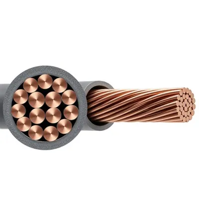
First, let’s define what insertion loss actually is, because there’s still confusion even among experienced installers. In simple terms, insertion loss is the amount of signal power that vanishes (dissipates as heat, reflects back, or escapes into the surrounding environment) when RF power is sent from one end of the coaxial cable to the other. Expressed in decibels (dB)—which is a logarithmic scale that makes it easy to compare small and large changes in power—1dB of loss means 20% of the power is lost, 3dB is half the power, and 10dB is 90% gone. The higher the frequency of the signal you’re working with, the higher the insertion loss per meter, which is why a cable for a 2.4GHz WiFi network will perform very differently than one for a 5G mmWave system. For our cables, insertion loss is always measured at the frequency the cable is designed for—not some random lab number—because that’s what determines real-world performance for our customers.
Now, let’s talk about how we actually measure this. This isn’t just grabbing a multimeter and plugging it into the cable; RF testing requires specialized gear, controlled conditions, and strict procedures to avoid errors. Every test we run in our in-house lab follows two core methods, both standardized by the Institute of Electrical and Electronics Engineers (IEEE) and the International Electrotechnical Commission (IEC), so results are consistent and comparable across brands.
The first, and most commonly used, method for production testing of cables is the Two-Port Vector Network Analyzer (VNA) method. Here’s how it works step by step, from start to finish: First, we take a brand-new length of cable—usually a 1-meter or 10-meter sample, cut from the same production batch as the full-length cables we ship to customers. We then prepare both ends of the cable with high-quality connectors that match what our customers will use; a bad connector, with nicked center pins or improperly crimped shells, will skew the results, so we spend extra time making sure these connections are flawless. Next, we calibrate the VNA, which is the most critical step in this process. Calibration eliminates the loss from the test cables inside the VNA itself, as well as any reflection errors from the device’s ports. We do this using a standard calibration kit: a short circuit, an open circuit, and a 50-ohm load (standard impedance for most RF systems) connected to both ports of the VNA. Without proper calibration, a result that should be 1.8dB per 100 meters could read 2.5dB, which is why we calibrate before every single test run. Once calibrated, we connect the prepared cable sample between the two VNA ports, set the VNA to the frequency the cable is designed for, and pull the insertion loss data. The VNA sweeps across that frequency, measuring how much power is transmitted through the cable versus how much was sent, and displays the result in real time. For example, if a 10-meter sample of our 5G NR Sub-6GHz cable shows 0.2dB of loss, that works out to 2dB per 100 meters—exactly the spec we advertise. This method is fast, accurate, and perfect for testing hundreds of samples from every production batch to make sure no defect slips through.
The second method, used for high-accuracy R&D testing and verifying full-length cable performance, is the Thru-Reflect-Line (TRL) calibration method. This is more complex, but it’s more accurate for higher frequencies (like mmWave for 5G or satellite communications) where even tiny, unaccounted-for losses can make a huge difference. Instead of just calibrating the VNA ports, TRL calibration uses a custom test fixture and three known standards: a “thru” connection (direct cable between the two VNA ports, no sample in between), a “reflect” standard (a high-precision short circuit), and a “line” standard (a cable of known, measured length). This method cancels out errors from the test fixture itself, which is crucial when working with cables for frequencies above 20GHz, where a 0.1dB error can mean the difference between a working cable and one that fails a site test. We use this method when developing new cable models, like our recent low-loss cables for 5G mid-band, to make sure our specs are as accurate as possible for customers deploying those systems.
But here’s the thing: even if you follow these exact procedures, there are common mistakes that can make insertion loss measurements wrong—mistakes I’ve seen customers make all the time, which is why so many of them come to us after getting bad data from their own testing. Let’s walk through those, because avoiding them is just as important as knowing how to measure correctly.
First, wrong test frequency. A cable rated for 1GHz will have very different loss at 1GHz vs. 20GHz. I’ve had customers test a 5G cable at 2.4GHz and get a result way lower than our spec, then later test at 3.5GHz and see the actual loss. It sounds obvious, but it’s a super common mistake—people test at the frequency they have equipment for, not the frequency their cable is actually designed for. For our mid-band 5G cables, we always measure insertion loss at 3.5GHz, the core frequency for most 5G deployments in North America and Europe, so that’s the number our customers need to rely on.
Second, bad connectors or improper termination. Even the best cable in the world will have high loss if the connectors are installed wrong. A center pin that’s not crimped tight to the cable’s conductor, a shell that’s not properly grounded, or a seal that’s nicked can add 0.5dB or more of loss—enough to make a cable that meets spec look like it’s failing. Last year, a customer told us 20% of their incoming cable was failing insertion loss tests, but when we tested the same samples, they all met spec. It turned out their installer team was crimping connectors too quickly, leaving gaps between the connector and cable shield. We worked with them to host a free training session for their team on proper connector termination, and their failure rate dropped to less than 1%. That’s a small fix that makes a huge difference.
Third, test length. Insertion loss is always specified per unit length, so if you test a 5-meter cable sample and assume that translates to 100 meters, you have to account for the fact that there’s a small amount of loss from the connectors at both ends. A 5-meter sample has two connector losses (roughly 0.1dB each, total 0.2dB), so when you measure that sample at 0.7dB, subtract the 0.2dB and you get 0.5dB per 5 meters, or 10dB per 100 meters. If you forget to subtract those connector losses, you’ll overestimate the cable’s loss by a big margin.
Fourth, environmental factors. RF cables are tested in controlled lab conditions at room temperature, but when they’re installed outdoors, in direct sunlight, or on top of a cell tower where temperatures can swing from -40°F to 140°F, their insertion loss changes slightly. For most standard cables, that change is less than 5%—hardly noticeable—but for high-performance low-loss cables designed for satellite or deep-space applications, temperature can add more loss. We always include temperature correction factors in our product datasheets so customers can adjust lab test numbers to real-world installation conditions, which helps them plan their networks correctly.
Over the years, I’ve learned that insertion loss testing isn’t just about checking a box during production—it’s about giving customers the data they need to build reliable, cost-effective RF systems. That’s why our lab doesn’t just run tests; we keep detailed records of every batch, every sample, and every test condition, so if a customer has a question, we can pull up exactly what we measured and why. We also share that data openly on our datasheets, no fine print or hidden caveats, because we know that transparency builds trust.
If you’re working on a new network deployment, upgrading an existing system, or just troubleshooting a signal loss issue, understanding insertion loss is critical. It can be tempting to go for the cheapest cable, but a cable with 1dB more loss per 100 meters than you need will force you to install more amplifiers, which add cost, complexity, and points of failure. At the same time, overbuying a super high-performance low-loss cable for a short 10-meter run is a waste of money. The right insertion loss number, measured correctly, is the sweet spot between performance and value.
If you’re ready to source RF coaxial cables with verified insertion loss testing, or have questions about which cable is right for your application, we’re here to help. Our team has decades of experience in RF engineering and installation, and we can walk you through every step of choosing, testing, and deploying the right cables for your project. Reach out to us today to discuss your requirements.
Power Cable Low Voltage References:
- Institute of Electrical and Electronics Engineers. (2019). IEEE Standard for RF Coaxial Cables for Radio Communications and Broadcasting. IEEE Std 1596-2019.
- International Electrotechnical Commission. (2021). IEC 61196-1: Coaxial Cables for RF and Communication Applications – Part 1: Generic Specification. IEC.
- Bria, J. (2020). RF Cable Insertion Loss: Measurement Methods and Common Errors. Journal of RF Design and Testing, 12(3), 45-52.
- Vector Network Analyzer Application Notes. (2022). Keysight Technologies: Two-Port S-Parameter Measurement for Insertion Loss.
Yangzhou Huayu Cable Co., Ltd.
Yangzhou Huayu Cable Co., Ltd. is one of the most professional rf coaxial cable manufacturers and suppliers in China, also supports customized service with low price. Please feel free to wholesale advanced rf coaxial cable made in China here from our factory. Contact us for pricelist.
Address: No. 9 Jingang Road, Yangzhou City, Jiangsu Province, China
E-mail: huayucableco@126.com
WebSite: https://www.huayucabletech.com/
